Research
Current Research
Mechanics of Nanostructures
Laser Generated Flyer Plate Impacts
Photonic Doppler Velocimetry
Blast Pressure Tests on Polymers
Adhesion Tests of Living Cancer Cells
Past Research
Laser Spallation Technique
Nanostructures under Shockwaves
Polymers for Impact Applications
Biomechanical Research Topics
Mechanics of Nanostructures
Materials behave differently at small domain sizes. In the past decade, tremendous research has been done in studying the effect of size on material properties, using nano-compression or tension tests on a wide range of nano structures of crystalline metals and amorphous solids. These tests help uncover the fundamental deformation processes involved due to the coupled effect of size, temperature, and loading rates.
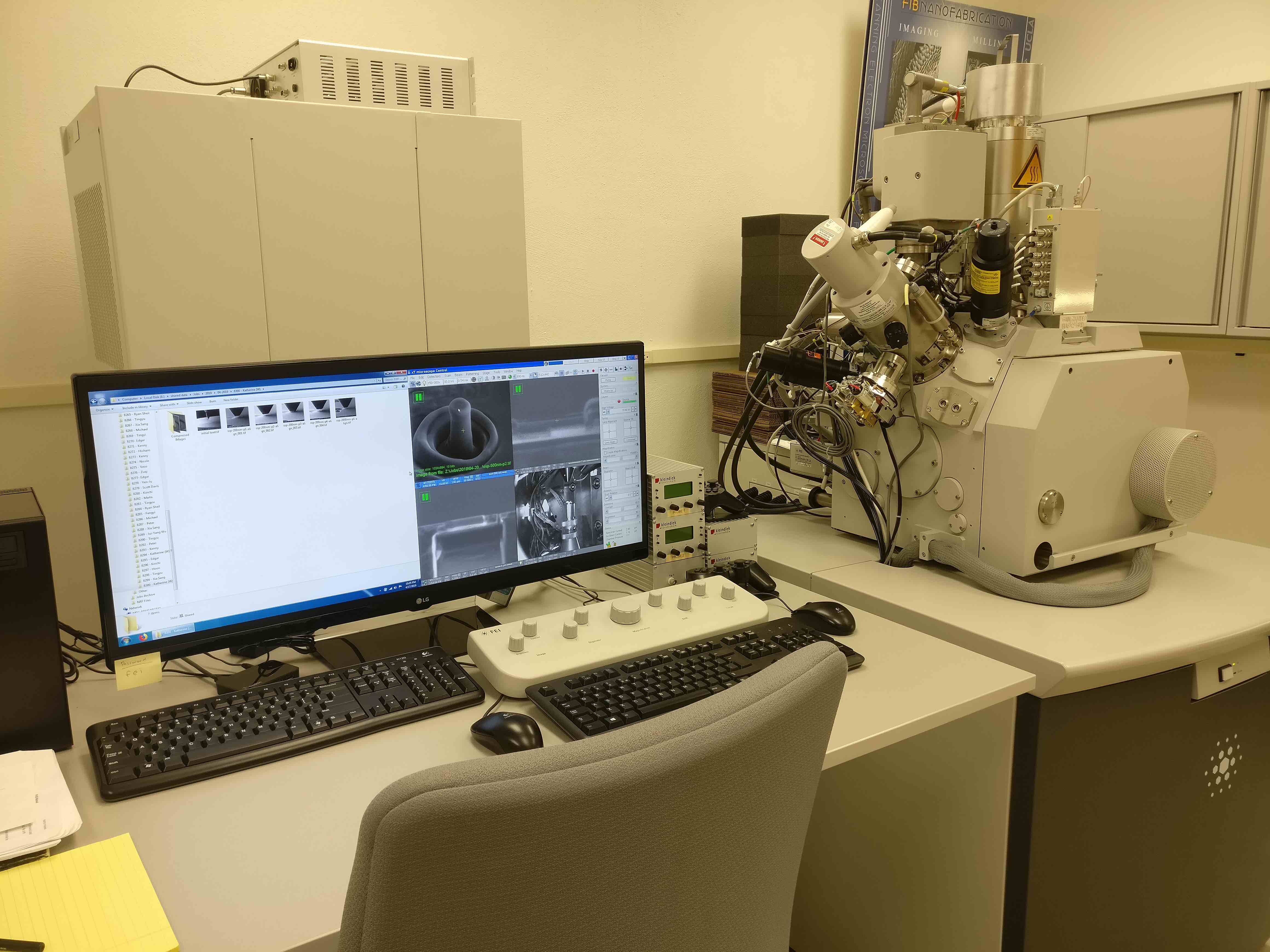
Our research aims to study these processes and quantify the material behavior such as temperature or strain rate sensitivity of the flow stress, strain hardening rates, strain bursts / dislocation avalanches statistics, etc. Using the Nanofabrication Research Facility at UCLA, we prepare nanostructures (nano-pillars, beams, etc.) for FCC and BCC metal single crystals using the Focused Ion Beam method, and perform in-situ SEM compression, tensile, and bending tests on these nanostructures. Post deformation samples are analyzed using scanning and transmission electron microscope images using the California NanoSystems Institute facility at UCLA.
In order to test the nanostructures under extreme conditions of temperature (cryogenic) and/or strain rates (108 s-1), we load these FIB prepared samples by laser generated shock waves, either using the modified laser spallation setup or the laser generated flyer plate setup. The stress levels are measured using laser interferometry (PDV) and the deformations are analyzed using SEM and TEM images.
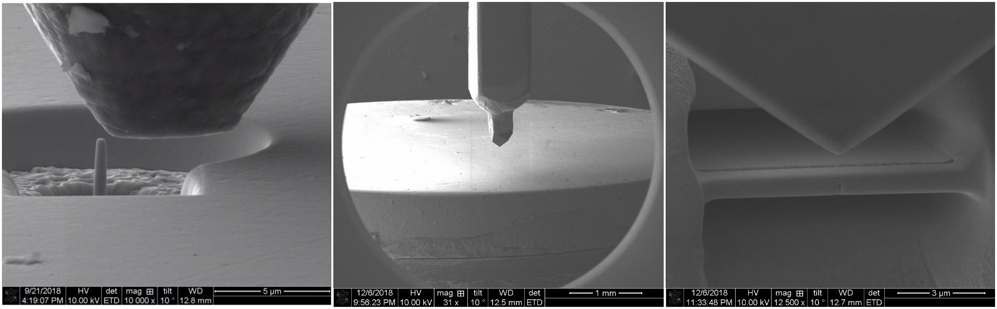
Nanostructure test images.
Laser Generated Flyer Plate Impacts
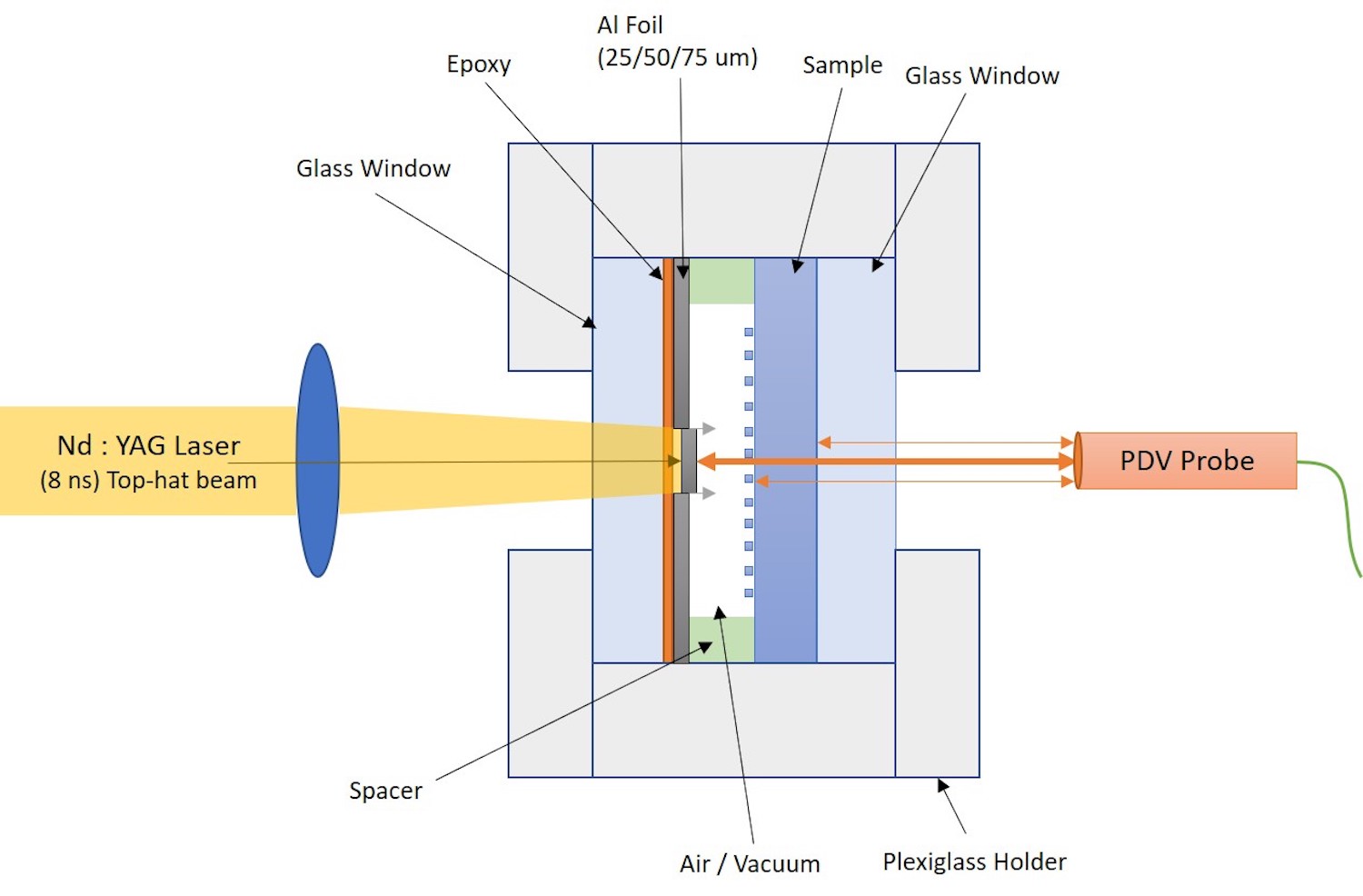
This setup is a miniaturized version of the plate impact experiments performed by gas guns, rail guns, and other large-scale shock setups. The laser launched plates produce shocks with duration shorter than the gas gun experiments. The setup is composed of three parts: laser drive source, foil-sample assembly, and photonic doppler velocimetry. Laser pulse (8 ns long) is used to detach thin flyer plates (discs) from metal foil bonded to a transparent window substrate. To maintain the integrity of the flyer throughout its flight, the laser beam profile is converted from gaussian to “top-hat” using diffractive optics. Foil thickness ranges from 10 microns to 100 microns. The diameter of these flyer plates ranges from 500 microns to 2 mm. The setup has the capability to launch these flyers at speeds up to 5 km/s. This brings the shock compression to the laboratory benchtop. Applications: Hugoniot EOS measurements, Shock-induced polymorphic transformations, Ultra-high strain rate deformation for nano-structures, etc.
Bench Setup for LGFP Impacts.
Photonic Doppler Velocimetry
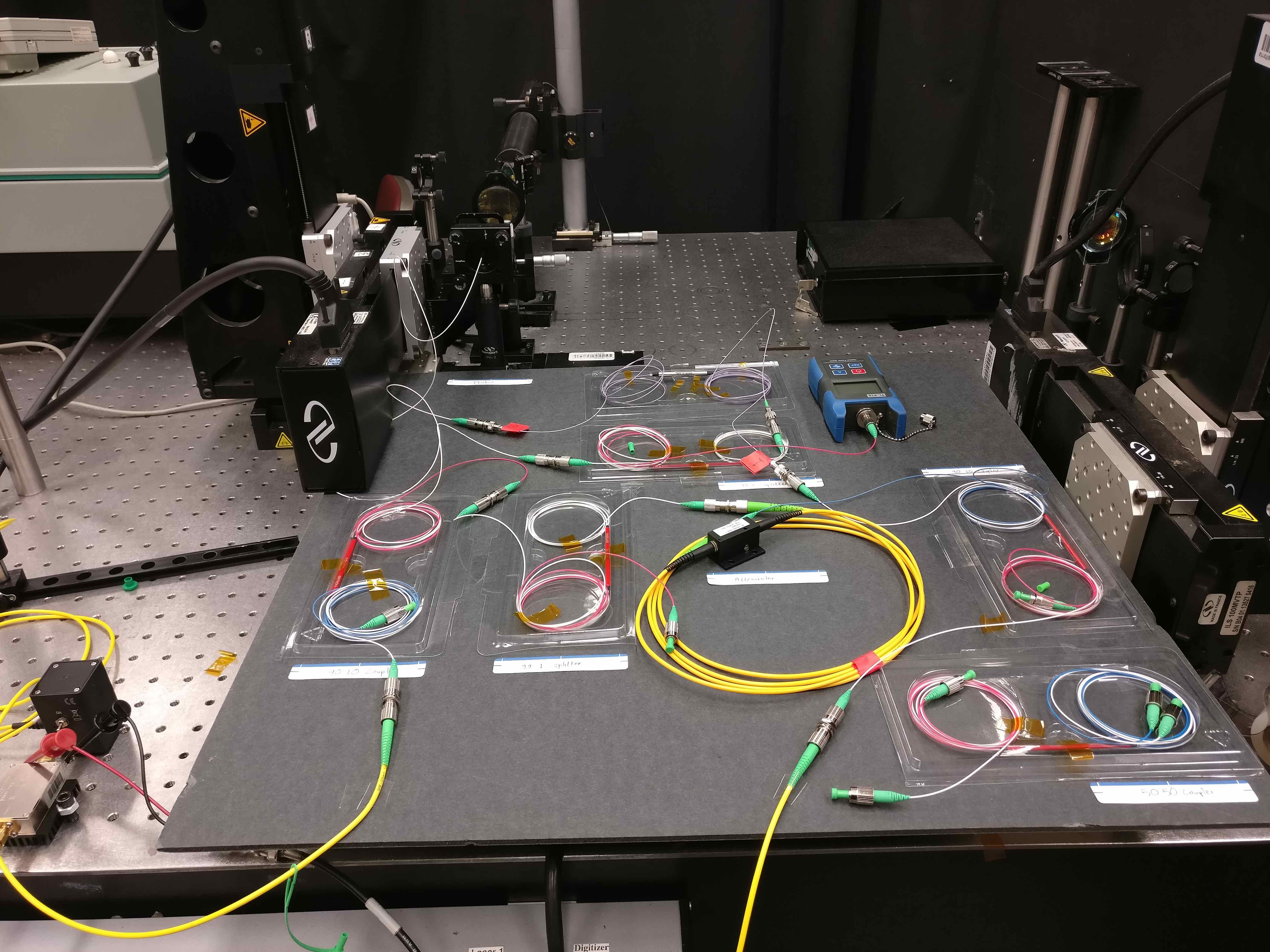
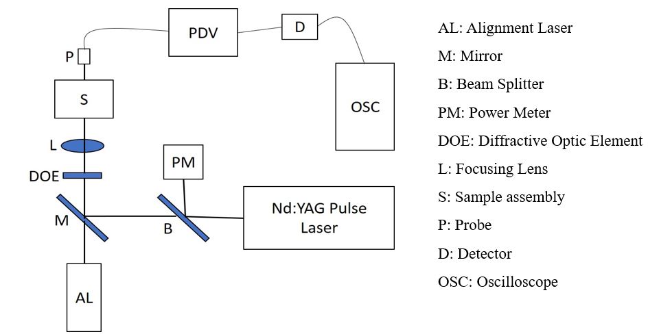
Photonic Doppler Velocimetry (PDV) relies on interference properties of light to measure ultra-fast velocities. A coherent laser source illuminates a moving target. The light that is reflected off the moving target is Doppler shifted, or in other words, has a different frequency and wavelength than the source light. The Doppler shifted signal is mixed with the source light. These two signals interfere and create a beat frequency. This interference beat frequency is proportional to the velocity of the target. Fiber-optic components are used to transmit and collect the signals. Our PDV system is used to measure the velocity of small aluminum flyer plates (see here for description of flyer plate experiments). We currently measure velocities up to 1.5 km/s.

Bench Setup for PDV.
Blast Pressure Tests on Polymers
In collaboration with the Office of Naval Research and Spearrin Lab (P.I. Mitchell Spearrin, UCLA), we are characterizing polyurea foam under shock loading conditions and evaluating its ability to attenuate pressure shock waves. Our setup attempts to model the scenario in which an individual wearing a combat helmet experiences the pressure shock from a nearby explosion. A shock tube in Professor Spearrin’s lab provides a pressure shock, which travels down the tube towards our foam sample. Our sample is sandwiched between a thin aluminum plate and a piece of polycarbonate plastic, which primitively model the outer surface of a helmet, and the skull, respectively. A sensor on the back plate of the tube records the force transmitted through the foam. Future plans include incorporating our PDV setup (see here) to capture displacement data to fully characterize the foam material.

Shock Tube and Sample Setup Device.
Adhesion Tests of Living Cancer Cells
Evaluation of the technique for measuring adhesion of living bone cells to polystyrene substrates:
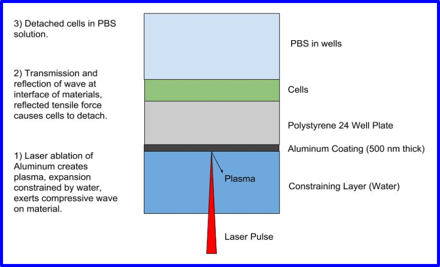
Cell adhesion to material surfaces is one of the fundamental phenomena of cellular response to implanted devices. Controlling the strength, dynamics, and mechanics of cell adhesion offer opportunities for designing novel biomaterials for tissue engineering and biotechnology. Many techniques have been developed for quantifying various types of cell–biomaterial interaction. One method to evaluate cell affinity for a biomaterial is to measure the stress required to remove adherent cells from the material. This study investigates the possibility of using laser spallation, a technique previously developed for measuring the tensile strength of thin film interfaces, for evaluation of initial cell attachment strength. MC3T3-E1 preosteoblasts were cultured on fibronectin-coated polystyrene, a surface known to engage cells in receptor mediated adhesion, and untreated polystyrene, which elicit nonspecific adhesion mechanisms during early stages of cell attachment. The laser spallation technique effectively detached cells from polymer substrates and distinguished relative cell adhesion strengths to surfaces with known differences in cell binding affinities. Scanning electron micrographs determined that cell detachment resulting from laser spallation left a cleaner surface than jet impingement, possibly suggesting a more complete detachment mechanism.
Current ongoing research is to quantify the adhesion strength of living cancer liver cells and comparison with different post-treatment cell samples.
Lab Setup for Cell Test.
The Laser Spallation Technique
Background of The Laser Spallation Technique

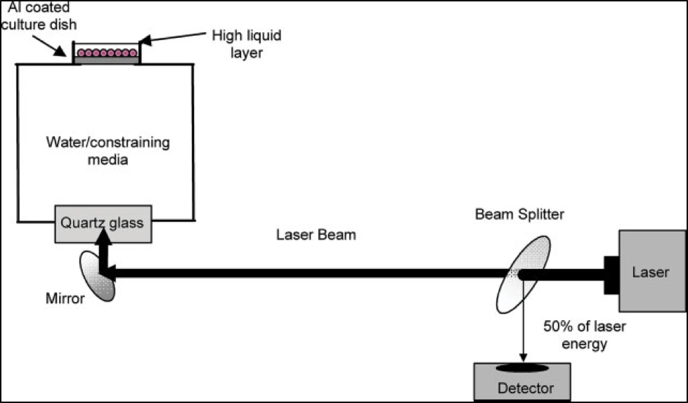
Schematic of The Laser Spallation Technique.
A method for characterizing interfacial adhesion is through laser driven shocks of thin films. This is a fundamental technique that quantifies interfacial adhesion. In the laser spallation experiment (shown in figure to the right) developed to measure the tensile strength of a thin film interface, a 2.5 nanosecond (ns) long Nd:YAG laser pulse is impinged over a 3 mm-dia area on a 0.5 µm thick Al film sandwiched between the back surface of a substrate disc (25 mm diameter and 1 mm thick) and a 50 to 100 µm thick layer of SiO2. The melting- induced expansion of Al under confinement generates a compressive stress wave (with 1 ns rise time) directed towards the test coating, which is deposited on the substrate's front surface. The compression stress pulse reflects into a tensile wave from the coating's free surface and leads to its spallation (complete removal) at a sufficiently high amplitude. During this film separation process, the transient free surface velocity of the coating is continuously recorded using a state-of-the art optical interferometer, a schematic of which is shown in the figure to the right. Optical fringes corresponding to stress pulses of 1-2 ns rise-time and 16-20 ns total duration are recorded in a single shot mode, with a resolution of 5 ps! In addition, the patented design of the interferometer can handle reflection from optically rough surfaces.
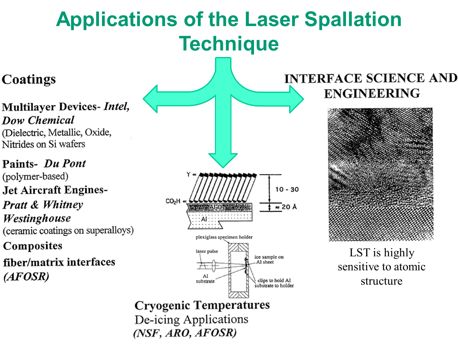
Applications of the Laser Spallation Technique
Next, the recorded fringe information is reduced to transient free surface velocity profile v(t), and is used to calculate the normal interfacial tensile stress in the following manner. For a coating of density ρ and thickness h, the interface stress σ is calculable from the measured transient velocity v(t).Because of high strain rate loading conditions, all inelastic effects are largely suppressed during interface decohesion, and thus, the measured strengths are intrinsic and related directly to the atomic microstructure and chemistry of the interfacial region. This was exemplified by measuring the tensile strengths of Nb/sapphire interfaces whose structure and chemistry were characterized using high resolution transmission electron microscopy and modified by a combination of heat treatment and deposition of 5 to 40 Å thick interlayers of Cr and Sb. Thus, atomic-scale tailoring of the interfacial region for either maximizing or reducing adhesion can be accomplished. Using this technology, interfacial strengths in the range of 0.1 GPa (14.5 ksi) to 2.5 GPa (362 ksi) have been measured in a variety of engineering systems (paints, multilayer electronic devices, engines, tribology) involving metal, ceramic and polymeric coatings deposited on metal, semiconductor and ceramic substrates.
Measurement of Thin Film Adhesion
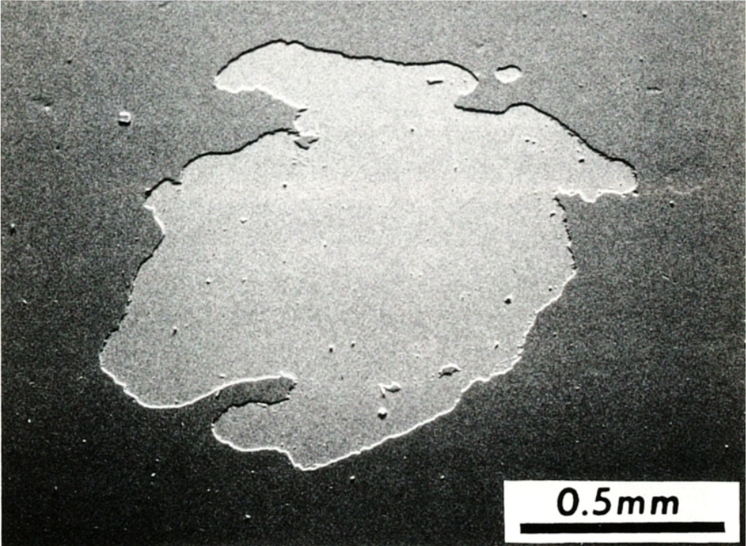
A spalled spot of a SiC coating from a Si substrate via the Laser Spallation Technique.
A laser spallation experiment has been developed to measure the strength of planar interfaces between a substrate and a thin coating (in the thickness range of 0.3-3 µm). In this technique a laser pulse of a high enough energy and a pre-determined duration is converted into a pressure pulse of a critical amplitude and width that is sent through the substrate toward the free surface with the coating. The reflected tensile wave from the free surface of the coating pries-off the coating. The critical stress amplitude that accomplishes the removal of the coating is determined from a computer simulation of the process. The simulation itself is verified by means of an interferometry process that is capable of mapping out the profile of the stress pulse generated by the laser pulse. Interface strength values ranging from 0.1 to 2.5 GPa have been determined for various thin film systems system.
Measurement of Joint Strength

The interface strength of an E-glass/polymer composite as a function of exposure time at 50°C and 90% RH.
The dynamic tensile strengths of various joints have been analyzed. One study included E-glass
composite/polymer and polymer/steel interfaces within the E-glass composite/polymer/AL-6XN stainless steel joint were measured using a laser
spallation technique. Values were obtained for the polymer/composite interface while a much higher value was obtained for the steel/polymer
interface. Because of the transient nature of the stress pulse, the strain rate changes continuously as the interface stress builds up. A peak
strain rate of 5 x 10⁵ s-1 was estimated. The effect of moisture on the tensile strength of the E-glass/polymer interface
was also examined. The effect was found to be minimal, with the tensile strength stabilizing after 30 days of exposure to a 90%RH, 50°C
environment. When comparing the strengths of corresponding interfaces in an epoxy-bonded joint from a previous study, it was concluded that our polymer results in a much stronger and durable joint.
Nanostructures under Shockwaves
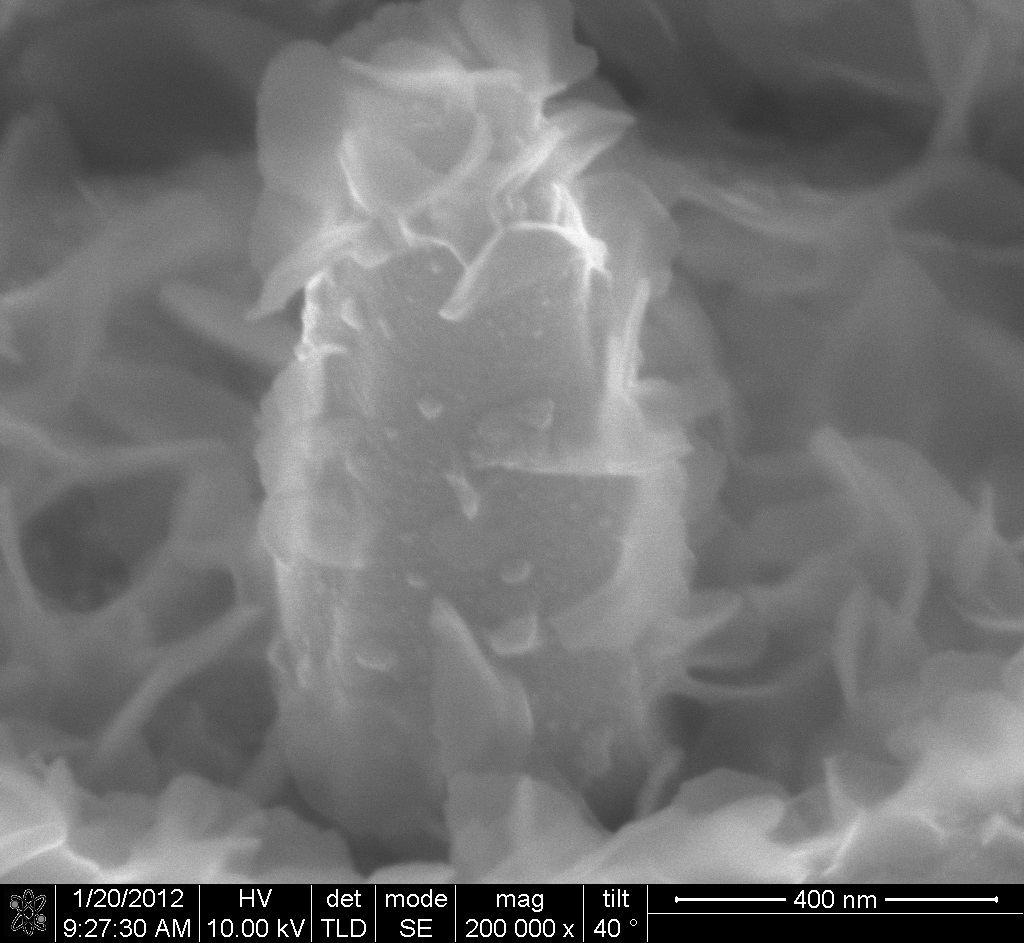
Scanning Electron Microscope image of copper nano-pillar 36 hours after shock loading.
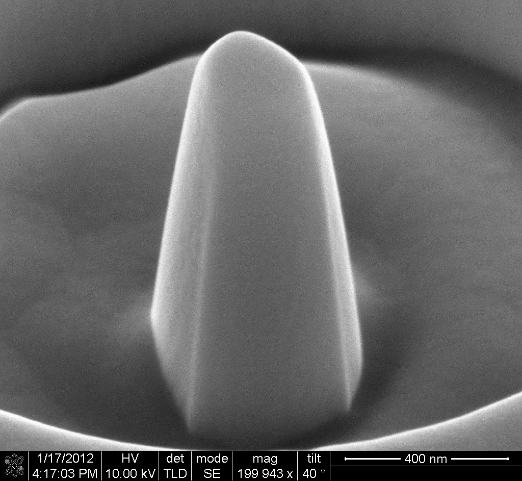
Scanning Electron Microscope image of reference copper nano-pillar.
The deformation of metals subjected to ultra-high strain rates, in excess of 107 s-1, is associated with a variety of unique physical phenomena, not normally observed in metals deformed at lower strain rates. Additionally, nanostructured materials are now recognized to exhibit extreme strength, reversible plasticity and dislocation-free twin boundary motion. In this study, a combination of laser-generated shockwave experiments, TEM observations, and Molecular Dynamics (MD) simulation are used to study the dynamic response of several nanostructured fcc metals when loaded at extremely high strain rates. MD simulation conditions are remarkably close to those achieved experimentally, allowing for direct interpretation of collective atomic motion and associated defect structures. The combination of nano-geometry and nanosecond rise-time stress waves is able to deform the material at stress (50 GPa) and strain rate (in excess of 107 s-1) levels never accomplished before. Two different loading setups are shown below.
Chemical Activation of Copper Nanopillars under Longitudinal Loading
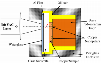
Set-up for Copper Nanopillars via Longitudinal Loading
ch An apparatus and test procedure for fabrication and loading of single crystal metal nanopillars under
extremely high pressures (>1 GPa) and strain rates (>107 s-1), using laser-generated stress waves, are presented.
Single-crystalline Cu pillars (~1.20 µm in tall and ~0.45 µm in diameter) prepared via focused ion beam milling of Cu(001)
substrates are shock-loaded using this approach with the dilatational stress waves propagating along the [001] axis of the pillars. Transmission electron microscopy observations of shock-loaded pillars show that dislocation density decreases and that their orientation changes with increasing stress wave amplitude, indicative of dislocation motion. The shock-loaded pillars exhibit enhanced chemical reactivity when submerged in oil and isopropyl alcohol solutions, due likely to the exposure of clean surfaces via surface spallation and formation of surface steps and nanoscale facets through dislocation motion to the surface of the pillars, resulting in growth of thin oxide films on the surfaces of the pillars.
Bending of Copper Pillars via Transverse Loading
Set-up for Copper Nanopillars via Transverse Loading
An experimental study to bend FIB-prepared cantilevered single crystal Cu nanopillars of several hundred
nanometers in diameter and length at ultrahigh strain rate is presented. The deformation is induced by laser-generated stress waves, resulting in local strain rates exceeding 107 s-1. Loading of nano-scale Cu structures at these extremely short loading times shows unique deformation characteristics. At a nominal stress value of 297 MPa, TEM examination along with selected area electron diffraction characterization revealed that twins within the unshocked Cu pillars interacted with dislocations that nucleated from free surfaces of the pillars to form new subgrain boundaries. MD simulation results were found to be consistent with the very low values of the stress required for dislocation activation and nucleation because of the extremely high surface area to volume ratio of the nanopillars. Specifically, simulations show that the stress required to nucleate dislocations at these ultrahigh strain rates is about one order of magnitude smaller than typical values required for homogeneous nucleation of dislocation loops in bulk copper single crystals under quasi-static conditions.
TEM bright-field images of the nanopillar before (a) and after laser shot at 320 mJ (b) and 450 mJ (c). Insets show corresponding diffraction patterns taken from the tip of the pillar. Scale bars in all images are 200 nm.
Polymers for Impact Applications
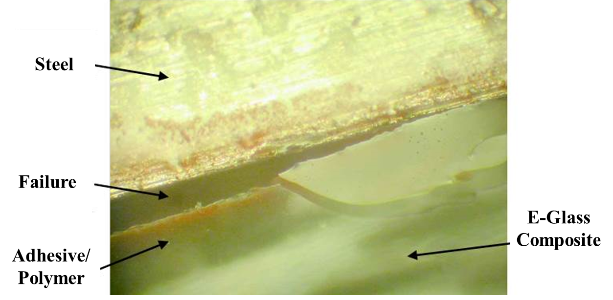
A micrograph showing the failure at the steel/polymer interface. Similar to the fracture energy measurements, the effect of moisture in the polymer-bonded samples was minimal with the interface tensile strength stabilizing at 320 ± 20 MPa after 30 days of exposure at 50°C and 90% RH environment.
Our research began by introducing a polymer as an adhesive for joining E-glass and stainless steel substrates. A recipe was discovered that resulted in a joint stronger than one of its adhered. Experiments to characterize the intrinsic and total fracture energies of the joints under both static and dynamic loads have been studied. The effect of hygrothermal loads is also discussed and shows that joints with this polymer remain virtually undamaged by such loads. Next, ultrahigh strain rate constitutive behavior of our polymer is presented at peak strain rates of 107 s-1 under pure tension and combined pressure-shear and tension-shear loads by subjecting thin polymer layers to laser generated stress waves of several nanoseconds in duration. We also studied the application of the polymer in multilayer armor design by showing two unusual effects. First, a sample flipping effect, in which polymer/foam bilayer specimens show almost a 40% reduction in their impact resistance depending upon which face bears the impact, and a second, resonance effect, when thin polymer layers are sandwiched between acrylic and polycarbonate plates.
Dynamic Strength and Fracture Toughness of Polymer Joints
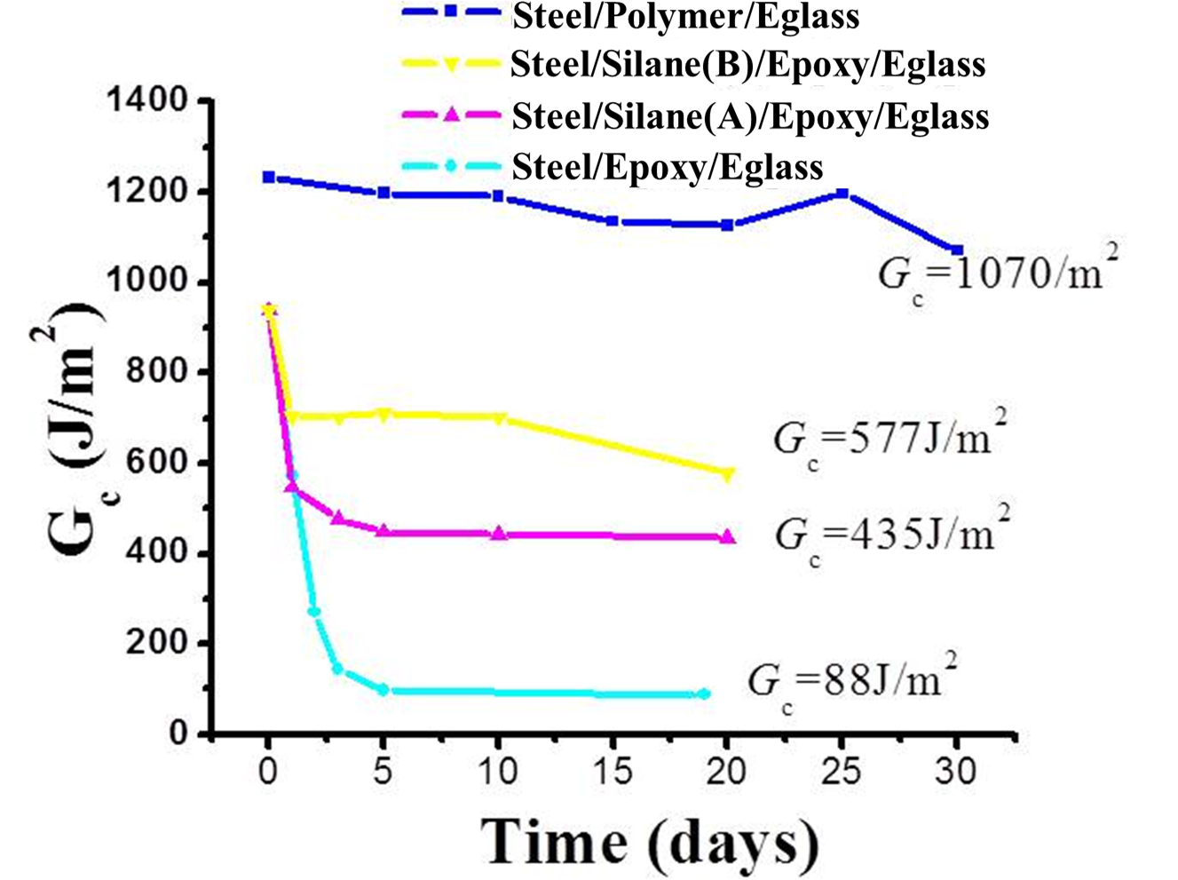
Comparison of the fracture energy values for the E-glass/Hysol epoxy and E-glass/polymer interfaces as a function of sample exposure times at 90% RH and 50°C.
Our research on this polymer started nine years ago. In the beginning, the research was motivated by the
desire to find a durable adhesive to join AL-6XN stainless steel plates and E-glass composite sections for lightweight ship construction that
could withstand static and dynamic loads during ship operation. To that challenge, a polymer chemistry was designed that resulted in failures
within the E-glass composite section, away from the joint, when the bonded specimens were separated using a double cantilever beam (DCB)
experiment. Additionally it was shown that hygrothermal loads did not degrade the mechanical integrity of the steel/polymer/E-glass joints as
their fracture energies were reduced from 1232 ± 15 J/m2 to 1070 ± 35 J/m2 when subjected to an accelerated
90% RH,
38°C environment for 30 days. In contrast, the fracture energy of the same joints constructed using the Hysol 9394 epoxy which is
widely
used in the aerospace industry underwent a 90% reduction from 950 J/m2 to 88 J/m2 when subjected to the same conditioning loads. To separate the size-related inelastic component of the fracture energy, DCB experiments were also carried out at the cryogenic temperature of 77 K to determine the intrinsic fracture energy value which can be used as a local failure criterion in large scale structural simulation of polymer joints.
Characterization of Polymer Impact Conditions
Since these joints are expected to perform under blast loads, their ability of resist dynamic loads was
also studied by measuring their tensile strength and fracture energy at extremely high rates of loading. This was accomplished by separating the
joints using well-characterized laser-generated stress waves of several nanoseconds in duration. Because of the sharp rise-time of the stress
pulse, failures in both experiments were accomplished at a peak strain rate approaching 106 s-1. Like the intrinsic
fracture energy, these values can be used to set the local failure criterion in design simulations of polymer joints subjected to dynamic loads.
To further aid the designer in determining the durability of these joints, these parameters were also measured in conditioned samples. Together
with the chemical recipe, the measurements of both the intrinsic and total fracture energies under static as well as dynamic loads provide a
complete set of parameters for designing and constructing durable polymer joints for large scale ship building and other structural
applications. Following studies were also extended to measure the dynamic tensile strength and fracture energy of the polymer by essentially using the same procedures except that the polymer layer on the steel substrate was chosen thick enough such that the returning tensile wave caused cohesive failure within the polymer volume. An average tensile strength of 93.1±5 MPa at a peak strain rate of 1.67 x 10⁷ s-1 and fracture energy of 6.75 J/m2 at a peak strain rate of 1.2 x 10⁷ s-1 were obtained.
Characterization of Polymer under High Strain Rate Stress Conditions
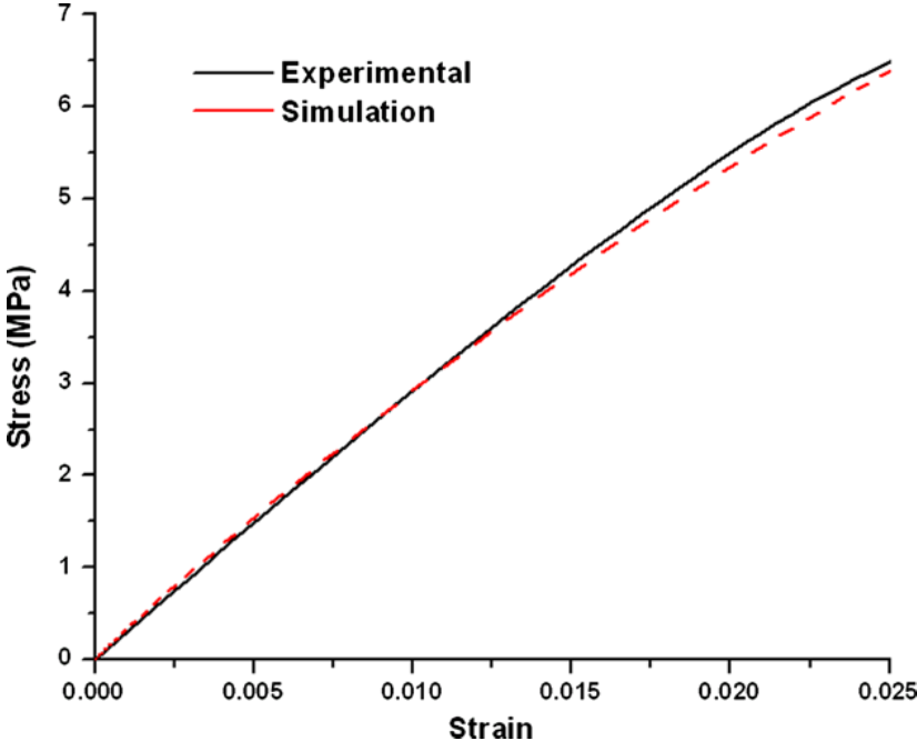
Comparison of the calculated (by TTS method) and experimentally derived stress-strain response for the polymer.
After developing and characterizing polymer joints that were stronger than one of the substrates
(E-glass composites), the project focus shifted to understanding the constitutive and fracture behavior of polymer at ultrahigh strain rates,
exceeding 105 s-1. This was motivated by the need for developing polymer-based armors against weapon in modern warfare,
such as shaped charges and explosively formed projectiles, which can attain speeds in the range of 2,500 to 9,000 m/s and therefore cause
dynamic loading within 50 ns upon impact. Since behavior at such high rates of loading cannot be studied even with the most sophisticated
plate-impact and split-Hopkinson bar setups, our goal was to first develop experimental procedures similar to those utilized in these tests and
then study the polymer behavior at such rates under pure tension, combined tension-shear, and combined pressure-shear loadings. Two major
effects were uncovered. First, it was demonstrated that the Time Temperature Superposition principle holds for the polymer even at strain rates
as high as 105 s-1. This strain rate is two orders of magnitude higher than those reported by Zhao et al. (2008) for the
similar phenomenon. This important finding suggests that blast simulations of large-scale structures and armors involving the polymer can be
based on constitutive data gathered under quasi-static conditions and translated to higher rates using the TTS principle.
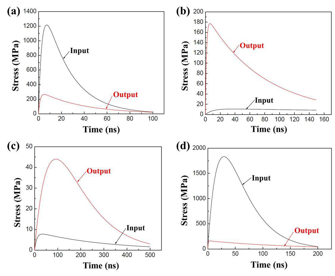
Interferometrically-reduced stress wave profiles measured in a (a) bare Al (input) plate and an Al/Polymer/Al sample (output) at an energy fluence of 311 mJ/mm2;(b) bare Acrylic (input) plate and an Acrylic/Polymer/Acrylic sample (output) at an energy fluence of 270 mJ/mm2; (c) bare Polycarbonate (input) plate and a Polycarbonate/Polymer/Polycarbonate sample (output) at an energy fluence of 310 mJ/mm2; and (d) bare tainless steel (input) plate and a Steel/Polymer/Steel sample (output) at an energy fluence of 310 mJ/mm2.
To study this, thin polymer layers were sandwiched between acrylic, glass, steel and Al plates and loaded with stress waves of 50 ns duration. The stress waves exiting the sections were compared with those entering the sections by the use of interferometry. An unusual resonance phenomenon was uncovered when the polymer layers were sandwiched between the acrylic and polycarbonate plates suggesting a substantial increase in the transmitted stress wave amplitudes contrary to a reduction that was expected. The expected results were however obtained when the polymer was sandwiched between Al and steel plates, each showing a dramatic reduction in the transmitted stress wave amplitude. Beside this ultrahigh rate testing, the effectiveness of the polymer in managing more traditional impacts in the low strain rate regime (103 s-1, or impulse loading over 1-50 ms range) were also studied by carrying out tests in a standard drop tower facility. To start, dense polymer sheets of 1-2 mm thickness were combined with commercially available foams to prepare bilayer specimens. A sample flipping effect was discovered which showed that the impact force was lower by up to 40% when the dense polymer layer was away from the striking impacter head. This observation, along with the discovered resonance effect, is very important to consider when designing polymer-based multilayer armors. Details pertaining to this research can also be found in Youssef & Gupta (2012) and Youssef & Gupta (2011).
Testing for polymer use in helmets
Professor Gupta's interview regarding use of a UCLA developed polymer in football helmets:
Video of helmet (left) and polymer (right) impact testing at the Dynamic Research Institute (DRI):
Biomechanical Research Topics
Biofilm Removal in Grossly Infected Wounds
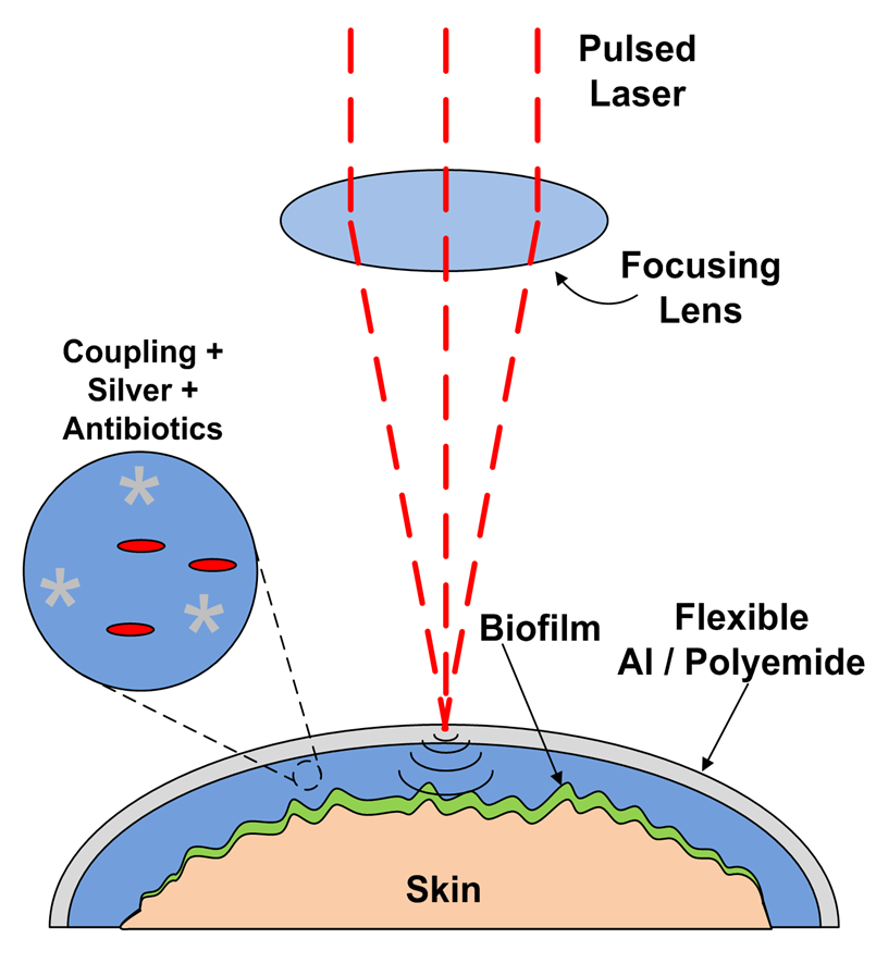
Schematic of proposed method of how to use laser generated shockwaves to delaminate and destroy biofilms.
Bacterial biofilm-related infections are a burden on the healthcare industry. The effect of laser generated shockwaves through polycarbonate, a flexible polymer, is explored for its ability to generate high peak stresses, and also for its ability to conform to complex wound surfaces. Shockwave pulses in Al coated polycarbonate substrates and a resulting peak stress of greater than 60 MPa was measured which should provide sufficient pressure to kill bacteria.
Biomechanics of a Cow Eye
Reported mechanical properties of orbital connective tissue and fat have been too sparse to model
strainstress relationships underlying biomechanical interactions in strabismus. We have performed rheological tests to develop a multi-mode
upper convectedMaxwell (UCM) model of these tissues under shear loading. From 20 fresh bovine orbits, 30 samples of connective tissue were taken
from rectus pulley regions and 30 samples of fatty tissues from the posterior orbit. Additional samples were defatted to determine connective
tissue weight proportion, which was verified histologically. Mechanical testing in shear employed a triborheometer to perform: strain sweeps at
0.52.0 Hz; shear stress relaxation with 1% strain; viscometry at 0.010.5 s1 strain rate; and shear oscillation at 1% strain. Average
connective tissue weight proportion was 98% for predominantly connective tissue and 76% for fatty tissue. Connective tissue specimens reached a
long-term relaxation modulus of 668 Pa after 1,500 s, while corresponding values for fatty tissue specimens were 290 Pa and 1,100 s. Shear
stress magnitude for connective tissue exceeded that of fatty tissue by five-fold. Based on this data, a multimode UCM model was developed with
variable viscosities and time constants, and a damped hyperelastic response that accurately described measured properties of both connective and
fatty tissues. Model parameters differed significantly between the two tissues. Viscoelastic properties of predominantly connective orbital
tissues under shear loading differ markedly from properties of orbital fat, but both are accurately reflected using UCM models. These
viscoelastic models now facilitate realistic global modeling of EOM behavior in binocular alignment and strabismus.
High Speed video analysis for Biomechanics of a Baseball Swing
Professor Gupta and a few of his graduate students took to using the lab's high speed video camera in order study the biomechanical effect of the axe-handle. Professor Gupta's report can be found here.
High-speed video of baseball impact utilizing traditional handle bat
High-speed video of baseball impact utilizing Axe handle bat